重现步骤
1.串口先发送a进入函数a
2.串口再发送b进入函数b(无法进入,报错)
期待结果和实际结果
希望可以实现两者功能的切换
软硬件版本信息
固件2.9.0
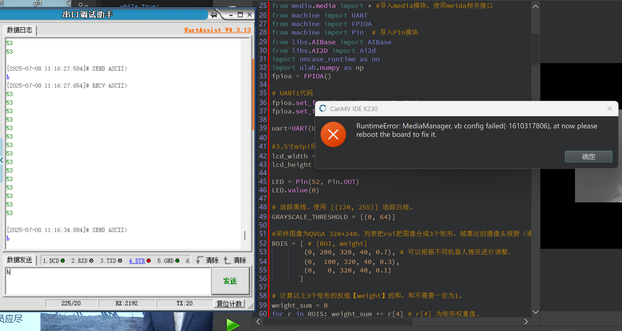
错误日志
RuntimeError: MediaManager, vb config failed(-1610317806), at now please reboot the board to fix it.
尝试解决过程
或者说可以通过逻辑代码实现按键的reset功能吗?
补充材料(完整代码)
见评论
重现步骤
1.串口先发送a进入函数a
2.串口再发送b进入函数b(无法进入,报错)
期待结果和实际结果
希望可以实现两者功能的切换
软硬件版本信息
固件2.9.0
错误日志
RuntimeError: MediaManager, vb config failed(-1610317806), at now please reboot the board to fix it.
尝试解决过程
或者说可以通过逻辑代码实现按键的reset功能吗?
补充材料(完整代码)
见评论
import time, os, utime, sys, math, gc, image, random, aicube
import ujson
from libs.PipeLine import PipeLine, ScopedTiming
from media.sensor import * #导入sensor模块,使用摄像头相关接口
from media.display import * #导入display模块,使用display相关接口
from media.media import * #导入media模块,使用meida相关接口
from machine import UART
from machine import FPIOA
from machine import Pin # 导入Pin模块
from libs.AIBase import AIBase
from libs.AI2D import Ai2d
import nncase_runtime as nn
import ulab.numpy as np
fpioa = FPIOA()
fpioa.set_function(3,FPIOA.UART1_TXD)
fpioa.set_function(4,FPIOA.UART1_RXD)
uart=UART(UART.UART1,115200) #设置串口号1和波特率
#3.5寸mipi屏分辨率定义
lcd_width = 800
lcd_height = 480
LED = Pin(52, Pin.OUT)
LED.value(0)
GRAYSCALE_THRESHOLD = [(0, 64)]
#采样图像为QVGA 320*240,列表把roi把图像分成3个矩形,越靠近的摄像头视野(通常为图像下方)的矩形权重越大。
ROIS = [ # [ROI, weight]
(0, 200, 320, 40, 0.7), # 可以根据不同机器人情况进行调整。
(0, 100, 320, 40, 0.3),
(0, 0, 320, 40, 0.1)
]
weight_sum = 0
for r in ROIS: weight_sum += r[4] # r[4] 为矩形权重值.
def a():
sensor = Sensor(width=1280, height=960) #构建摄像头对象,将摄像头长宽设置为4:3
sensor.reset() #复位和初始化摄像头
sensor.set_framesize(width=320, height=240) #设置帧大小,默认通道0
sensor.set_pixformat(Sensor.GRAYSCALE) #设置输出图像格式,默认通道0
Display.init(Display.ST7701, width=lcd_width, height=lcd_height, to_ide=True) #同时使用mipi屏和IDE缓冲区显示图像
#Display.init(Display.VIRT, sensor.width(), sensor.height()) #只使用IDE缓冲区显示图像
MediaManager.init() #初始化media资源管理器
sensor.run() #启动sensor
clock = time.clock()
while True:
    ################
    ## 这里编写代码 ##
    ################
    clock.tick()

    img = sensor.snapshot() #拍摄一张图片

    centroid_sum = 0

    for r in ROIS:
        blobs = img.find_blobs(GRAYSCALE_THRESHOLD, roi=r[0:4], merge=True) # r[0:4] 是上面定义的roi元组.

        if blobs:
            # Find the blob with the most pixels.
            largest_blob = max(blobs, key=lambda b: b.pixels())

            # Draw a rect around the blob.
            img.draw_rectangle(largest_blob.rect())
            img.draw_cross(largest_blob.cx(),
                           largest_blob.cy())

            centroid_sum += largest_blob.cx() * r[4] # r[4] 是每个roi的权重值.

    center_pos = (centroid_sum / weight_sum) # 确定直线的中心.

    # 将直线中心位置转换成角度,便于机器人处理.
    deflection_angle = 0

    # 使用反正切函数计算直线中心偏离角度。可以自行画图理解
    #权重X坐标落在图像左半部分记作正偏,落在右边部分记为负偏,所以计算结果加负号。

    #deflection_angle = -math.atan((center_pos-80)/60) #采用图像为QQVGA 160*120时候使用

    deflection_angle = -math.atan((center_pos-160)/120) #采用图像为QVGA 320*240时候使用

    # 将偏离值转换成偏离角度.
    deflection_angle = math.degrees(deflection_angle)

    # 计算偏离角度后可以控制机器人进行调整.
    print("Turn Angle: %d" % deflection_angle)

    # LCD显示偏移角度,scale参数可以改变字体大小
    img.draw_string_advanced(2,2,20, str('%.1d' % deflection_angle), color=(255,255,255))

    #Display.show_image(img) #显示图片

    #显示图片,仅用于LCD居中方式显示
    Display.show_image(img, x=round((lcd_width-sensor.width())/2),y=round((lcd_height-sensor.height())/2))

    #print(clock.fps()) #打印FPS
    uart.write("%d\n" % deflection_angle)#发送一条数据

    # 添加非阻塞模式切换检查
    new_text = uart.read(1)
    if new_text and new_text in [b'a', b'b']:
        print("退出巡线模式")
        sensor.stop()  # 停止摄像头
        MediaManager.deinit()  # 释放媒体资源
        break
def b():
# 添加显示模式,支持"hdmi"和"lcd"
display_mode="lcd"
if display_mode=="hdmi":
display_size=[1920,1080]
else:
display_size=[800,480]
kmodel_path="/sdcard/app/Test/TEST.kmodel"
# 根据数据集设置,在线训练平台和AICube部署包的deploy_config.json文件中包含该字段
labels=["1","2","3","4","5","6","7","8","9"]
# 类别置信度阈值
confidence_threshold=0.5
# nms阈值
nms_threshold = 0.5
# 训练中使用的锚框,在线训练平台和AICube部署包的deploy_config.json文件中包含该字段,只有AnchorBaseDet需要该参数
anchors=[30,23,21,33,29,43,44,29,41,39,41,68,71,43,59,61,71,72]
# 初始化PipeLine,只关注传给AI的图像分辨率,显示的分辨率
pl=PipeLine(rgb888p_size=[1280,720],display_size=display_size,display_mode=display_mode)
pl.create()
# 检测类实例,关注模型输入分辨率,传给AI的图像分辨率,显示的分辨率
det=DetectionApp(kmodel_path,labels,model_input_size=[640,640],anchors=anchors,rgb888p_size=[1280,720],display_size=display_size,debug_mode=0)
# 配置预处理过程
det.config_preprocess()
try:
while True:
os.exitpoint()
with ScopedTiming("total",1):
# 获取当前帧
img=pl.get_frame()
# 获得检测框
det_boxes=det.run(img)
# 绘制检测框和类别信息
det.draw_result(pl,det_boxes)
# 显示当前的绘制结果
pl.show_image()
gc.collect()
except BaseException as e:
print("Exception:", e) # 使用通用异常打印方式
# sys.print_exception(e) # 如果环境支持可用此方式
finally:
det.deinit()
pl.destroy()
class DetectionApp(AIBase):
def init(self,kmodel_path,labels,model_input_size=[640,640],anchors=[10.13,16,30,33,23,30,61,62,45,59,119,116,90,156,198,373,326],model_type="AnchorBaseDet",confidence_threshold=0.5,nms_threshold=0.25,nms_option=False,strides=[8,16,32],rgb888p_size=[1280,720],display_size=[1920,1080],debug_mode=0):
super().init(kmodel_path,model_input_size,rgb888p_size,debug_mode)
# kmodel路径
self.kmodel_path=kmodel_path
# 类别标签
self.labels=labels
# 模型输入分辨率
self.model_input_size=model_input_size
# 检测任务的锚框
self.anchors=anchors
# 模型类型,支持"AnchorBaseDet","AnchorFreeDet","GFLDet"三种模型
self.model_type=model_type
# 检测框类别置信度阈值
self.confidence_threshold=confidence_threshold
# 检测框NMS筛选阈值
self.nms_threshold=nms_threshold
# NMS选项,如果为True做类间NMS,如果为False做类内NMS
self.nms_option=nms_option
# 输出特征图的降采样倍数
self.strides=strides
# sensor给到AI的图像分辨率,宽16字节对齐
self.rgb888p_size=[ALIGN_UP(rgb888p_size[0],16),rgb888p_size[1]]
# 视频输出VO分辨率,宽16字节对齐
self.display_size=[ALIGN_UP(display_size[0],16),display_size[1]]
# 调试模式
self.debug_mode=debug_mode
# 检测框预置颜色值
self.color_four=[(255, 220, 20, 60), (255, 119, 11, 32), (255, 0, 0, 142), (255, 0, 0, 230),
(255, 106, 0, 228), (255, 0, 60, 100), (255, 0, 80, 100), (255, 0, 0, 70),
(255, 0, 0, 192), (255, 250, 170, 30), (255, 100, 170, 30), (255, 220, 220, 0),
(255, 175, 116, 175), (255, 250, 0, 30), (255, 165, 42, 42), (255, 255, 77, 255),
(255, 0, 226, 252), (255, 182, 182, 255), (255, 0, 82, 0), (255, 120, 166, 157)]
# Ai2d实例,用于实现模型预处理
self.ai2d=Ai2d(debug_mode)
# 设置Ai2d的输入输出格式和类型
self.ai2d.set_ai2d_dtype(nn.ai2d_format.NCHW_FMT,nn.ai2d_format.NCHW_FMT,np.uint8, np.uint8)
# 配置预处理操作,这里使用了pad和resize,Ai2d支持crop/shift/pad/resize/affine,具体代码请打开/sdcard/app/libs/AI2D.py查看
def config_preprocess(self,input_image_size=None):
with ScopedTiming("set preprocess config",self.debug_mode > 0):
# 初始化ai2d预处理配置,默认为sensor给到AI的尺寸,您可以通过设置input_image_size自行修改输入尺寸
ai2d_input_size=input_image_size if input_image_size else self.rgb888p_size
# 计算padding参数
top,bottom,left,right=self.get_padding_param()
# 配置padding预处理
self.ai2d.pad([0,0,0,0,top,bottom,left,right], 0, [114,114,114])
# 配置resize预处理
self.ai2d.resize(nn.interp_method.tf_bilinear, nn.interp_mode.half_pixel)
# build预处理过程,参数为输入tensor的shape和输出tensor的shape
self.ai2d.build([1,3,ai2d_input_size[1],ai2d_input_size[0]],[1,3,self.model_input_size[1],self.model_input_size[0]])
# 自定义当前任务的后处理,这里调用了aicube模块的后处理接口
def postprocess(self,results):
with ScopedTiming("postprocess",self.debug_mode > 0):
if self.model_type == "AnchorBaseDet":
# 修改所有labels为self.labels
det_boxes = aicube.anchorbasedet_post_process(results[0], results[1], results[2], self.model_input_size,
self.rgb888p_size, self.strides, len(self.labels), self.confidence_threshold,
self.nms_threshold, self.anchors, self.nms_option)
        elif self.model_type == "GFLDet":
            det_boxes = aicube.gfldet_post_process(results[0], results[1], results[2], self.model_input_size,
                self.rgb888p_size, self.strides, len(self.labels), self.confidence_threshold,
                self.nms_threshold, self.nms_option)

        elif self.model_type=="AnchorFreeDet":
            det_boxes = aicube.anchorfreedet_post_process(results[0], results[1], results[2], self.model_input_size,
                self.rgb888p_size, self.strides, len(self.labels), self.confidence_threshold,
                self.nms_threshold, self.nms_option)

        else:
            det_boxes=None
        return det_boxes

# 将结果绘制到屏幕上
def draw_result(self,pl,det_boxes):
    global uart

    with ScopedTiming("draw osd",self.debug_mode > 0):
        if det_boxes:
            pl.osd_img.clear()
            # 收集所有检测到的标签数字
            detected_labels = [self.labels[b[0]] for b in det_boxes]
            # 发送逗号分隔的数字字符串
            uart.write(f"{','.join(detected_labels)}\n".encode())

            for det_boxe in det_boxes:
                # 获取每一个检测框的坐标,并将其从原图分辨率坐标转换到屏幕分辨率坐标,将框和类别信息绘制在屏幕上
                x1, y1, x2, y2 = det_boxe[2],det_boxe[3],det_boxe[4],det_boxe[5]
                sx=int(x1 * self.display_size[0] // self.rgb888p_size[0])
                sy=int(y1 * self.display_size[1] // self.rgb888p_size[1])
                w = int(float(x2 - x1) * self.display_size[0] // self.rgb888p_size[0])
                h = int(float(y2 - y1) * self.display_size[1] // self.rgb888p_size[1])
                pl.osd_img.draw_rectangle(sx , sy , w , h , color=self.get_color(det_boxe[0]))
                label = self.labels[det_boxe[0]]
                score = str(round(det_boxe[1],2))
                pl.osd_img.draw_string_advanced(sx, sy-50,32, label + " " + score , color=self.get_color(det_boxe[0]))
        else:
            pl.osd_img.clear()
            pl.osd_img.draw_rectangle(0, 0, 128, 128, color=(0,0,0,0))
            # 无检测时发送"None"
            uart.write("None\n".encode())

# 计算padding参数
def get_padding_param(self):
    ratiow = float(self.model_input_size[0]) / self.rgb888p_size[0];
    ratioh = float(self.model_input_size[1]) / self.rgb888p_size[1];
    ratio = min(ratiow, ratioh)
    new_w = int(ratio * self.rgb888p_size[0])
    new_h = int(ratio * self.rgb888p_size[1])
    dw = float(self.model_input_size[0]- new_w) / 2
    dh = float(self.model_input_size[1] - new_h) / 2
    top = int(round(dh - 0.1))
    bottom = int(round(dh + 0.1))
    left = int(round(dw - 0.1))
    right = int(round(dw - 0.1))
    return top,bottom,left,right

# 根据当前类别索引获取框的颜色
def get_color(self, x):
    idx=x%len(self.color_four)
    return self.color_four[idx]
while True:
gc.collect()
text = uart.read(1)
if text == b'a':
print("进入巡线模式")
LED.value(1)
time.sleep(1)
LED.value(0)
a() # 执行巡线函数
elif text == b'b':
print("进入目标检测模式")
LED.value(1)
time.sleep(1)
LED.value(0)
b() # 执行检测函数

