
K230 Linux LCD Porting Guide#
This document only applies to K230 Linux SDK
Overview#
The VO (Video Output) module actively reads video and graphics data from memory and outputs through display devices. The K230 chip supports the following display/write-back devices and video layer configurations.
LAYER Layer Support#
Function |
LAYER1 |
LAYER3 |
LAYER4 |
|---|---|---|---|
Input Format |
YUV420 NV12 |
YUV420 NV12 |
YUV420 NV12 |
Max Resolution |
1920 x 1080 |
1920 x 1080 |
1920 x 1080 |
Overlay Display |
Supports configurable overlay order |
Supports configurable overlay order |
Supports configurable overlay order |
Rotation |
√ |
- |
- |
Scaler |
√ |
- |
- |
Mirror |
√ |
- |
- |
Gray Mode |
√ |
- |
- |
Independent Switch |
√ |
√ |
√ |
OSD Layer Support#
Function |
OSD0 |
OSD1 |
OSD2 |
OSD3 |
|---|---|---|---|---|
Input Format |
RGB888, RGB565, ARGB8888, Monochrome-8-bit, RGB4444, RGB1555 |
RGB888, RGB565, ARGB8888, Monochrome-8-bit, RGB4444, RGB1555 |
RGB888, RGB565, ARGB8888, Monochrome-8-bit, RGB4444, RGB1555 |
RGB888, RGB565, ARGB8888, Monochrome-8-bit, RGB4444, RGB1555 |
Max Resolution |
1920 x 1080 |
1920 x 1080 |
1920 x 1080 |
1920 x 1080 |
Overlay Display |
Supports configurable overlay order |
Supports configurable overlay order |
Supports configurable overlay order |
Supports configurable overlay order |
ARGB 256-level Alpha |
√ |
√ |
√ |
√ |
Independent Switch |
√ |
√ |
√ |
√ |
LCD Adaptation on Linux#
This chapter describes how to add a MIPI LCD screen in the K230 Linux SDK. The K230 configures the screen through the DSI interface using LP (Low Power) commands. The main changes required are in the device tree, specifically the screen initialization sequence and timing parameters.
Screen Initialization Sequence#
The screen initialization sequence corresponds to the device tree node panel-init-sequence. The format for each line of commands is as follows:
Byte Position |
0 |
1 |
2 |
3+ |
|---|---|---|---|---|
Meaning |
Command Type |
Delay |
Payload Length |
Data |
Parameter Description:
Parameter |
Description |
|---|---|
Command Type |
Command type (0x05: single byte data, 0x15: two-byte data, 0x39: multi-byte data) |
Delay |
Milliseconds to wait after command execution |
Payload Length |
Payload length in bytes |
Data |
Command data to write |
Command Example Analysis
// 39 00 04 ff 98 81 03
// Command Type: 0x39 (multi-byte), Delay: 0ms, Payload Length: 4 bytes
// Data: ff 98 81 03
//
// 15 00 02 01 00
// Command Type: 0x15 (two-byte), Delay: 0ms, Payload Length: 2 bytes
// Data: 01 00
//
// 05 00 01 35
// Command Type: 0x05 (single byte), Delay: 0ms, Payload Length: 1 byte
// Data: 35
//
// 05 78 01 11
// Command Type: 0x05 (single byte), Delay: 120ms (0x78), Payload Length: 1 byte
// Data: 11

panel-init-sequence = [
   39 00 04 ff 98 81 03
   15 00 02 01 00
   15 00 02 02 00
   15 00 02 03 53
   15 00 02 04 13
   15 00 02 05 00
   15 00 02 06 04
   // ... omitted ...
   15 00 02 ce 59
   15 00 02 cf 2c
   15 00 02 d0 30
   15 00 02 d1 55
   15 00 02 d2 6b
   15 00 02 d3 3f
   39 00 04 ff 98 81 00
   05 00 01 35
   05 78 01 11
   05 00 01 29
];
// For a complete example, refer to: arch/riscv/boot/dts/canaan/display-ili9881-800x1280.dtsi
Note: The screen initialization sequence is typically provided by the screen manufacturer and needs to be converted to the K230 device tree format.
Screen Timing Parameters#
LCD timing parameters are used to configure the DSI controller to match the screen’s timing requirements.
// Example: arch/riscv/boot/dts/canaan/display-st7701-480x800.dtsi
lcd: panel@0 {
    compatible = "canaan,universal";
    reg = <0>;
    display-timings {
        timing-0 {
            clock-frequency = <39600000>;
            hactive = <480>;
            vactive = <800>;
            hfront-porch = <80>;
            hback-porch = <20>;
            hsync-len = <20>;
            vfront-porch = <220>;
            vback-porch = <70>;
            vsync-len = <10>;
        };
    };
};
Field Description:
Field |
Description |
|---|---|
clock-frequency |
DSI pixel clock frequency (Hz). It is recommended to use the k230 screen timing tool for calculation |
hactive |
Active horizontal display width (pixels) |
vactive |
Active vertical display height (pixels) |
hfront-porch |
Horizontal front porch (bfp): the wait time between the end of a line of valid data and the start of the sync pulse |
hback-porch |
Horizontal back porch (hbp): the wait time between the end of the sync pulse and the start of the next line of valid data |
hsync-len |
Horizontal sync pulse width (hsa) |
vfront-porch |
Vertical front porch (vfp): the wait time between the end of a frame of data and the start of the vertical sync pulse |
vback-porch |
Vertical back porch (vbp): the wait time between the end of the vertical sync pulse and the start of the next frame of valid data |
vsync-len |
Vertical sync pulse width (vsa) |
Unit Description:
hsa, hbp, bfp, hactive are in pixels (pix)
vsa, vbp, vfp, vactive are in lines (line)
Other Screen Configuration Items#
// Example: arch/riscv/boot/dts/canaan/display-st7701-480x800.dtsi
lcd: panel@0 {
    compatible = "canaan,universal";
    reg = <0>;

    panel-width-mm = <480>;     // Physical screen width (mm)
    panel-height-mm = <800>;    // Physical screen height (mm)
    panel-dsi-lane = <2>;       // Number of DSI data lanes
};
Configuration Item Description:
Field |
Description |
Required |
|---|---|---|
panel-width-mm |
Physical screen width (unit: mm) |
Yes |
panel-height-mm |
Physical screen height (unit: mm) |
Yes |
panel-dsi-lane |
Number of DSI data lanes (2/4) |
Yes |
Note: The above parameters need to be configured according to the actual screen datasheet.
LCD Adaptation under U-Boot#
Note: LCD support under K230 U-Boot is primarily used for displaying the boot logo. It is generally not recommended to enable LCD in U-Boot. Currently, only the K230 01 Studio product has the Logo display feature enabled.
Adaptation Overview#
U-Boot only supports the 01 Studio screen. To support other screens, refer to the commit K230 01 Studio U-Boot supports ILI9881 8-inch screen.
Search for CONFIG_K230_BARE_DISP_LOGO_ILI9881 in the SDK to view the locations that need to be modified, which mainly include:
Screen initialization sequence
Screen timing parameters
VO configuration
Initialization Sequence#
The initialization sequence under Linux needs to be converted into a format similar to the following:
// buildroot-overlay/boot/uboot/u-boot-2022.10-overlay/board/canaan/common/logo/st7701.c
void ili9881_800x1280_init(void)
{
    // ILI9881 800x1280 initialization sequence from DTS
    // Page 0x03
    uint8_t param1[] = {0xff, 0x98, 0x81, 0x03};
    uint8_t param2[] = {0x01, 0x00};
    uint8_t param3[] = {0x02, 0x00};
    uint8_t param4[] = {0x03, 0x53};

    // ... other initialization parameters

    kd_dwc_lpdt_send_pkg(param202, sizeof(param202));
    msleep(100);
    kd_dwc_lpdt_send_pkg(param201, sizeof(param201));
    msleep(120);
    kd_dwc_lpdt_send_pkg(param202, sizeof(param202));
}
Timing and VO Configuration#
// buildroot-overlay/boot/uboot/u-boot-2022.10-overlay/board/canaan/common/logo/k230_logo.c
int k230_display_logo(void)
{
    info = (k_connector_info){
        0,
        BACKGROUND_PINK_COLOR,
        10,
        14,
        1,
        K_DSI_2LAN,
        K_BURST_MODE,
        K_VO_LP_MODE,
        { 9, 196, 0x17, 0xa3 },
        { 39600, 475200, 600, 480, 20, 20, 80, 1100, 800, 10, 70, 220 },
    };
}
Note: Please use the k230 screen timing tool to calculate the parameters before converting and filling them in.
Resolution Setting#
To set the screen resolution in U-Boot, refer to the following code snippet:
// buildroot-overlay/boot/uboot/u-boot-2022.10-overlay/board/canaan/common/logo/display_logo.c
void vo_layer1_test(k_connector_info *info)
{
    uint32_t reg = 0;
    #ifdef CONFIG_K230_BARE_DISP_LOGO_DF
        uint32_t act_w = 480;
        uint32_t act_h = 640;
    #elif defined(CONFIG_K230_BARE_DISP_LOGO_ILI9881)
        uint32_t act_w = 800;
        uint32_t act_h = 1280;
    #else
        uint32_t act_w = 480;
        uint32_t act_h = 800;
    #endif
    // ...
}
Reset and Backlight#
//buildroot-overlay/boot/uboot/u-boot-2022.10-overlay/board/canaan/common/logo/st7701.c
    #define GPIO_RST_PIN            24  //modify to the correct value
    #define GPIO_LCD_BACKLIGHT_EN   25  //modify to the correct value
Note: If the logo is enabled in uboot, the following similar code needs to be commented out under linux:
//output/k230_canmv_01studio_defconfig/build/linux-7d4e1f444f461dbe3833bd99a4640e7b6c2cd529/arch/riscv/boot/dts/canaan/>k230-canmv-01studio-lcd.dts
&lcd
{
    // dsi_reset-gpios = <&gpio0_ports 24 GPIO_ACTIVE_HIGH>;
    // backlight_gpio-gpios = <&gpio0_ports 25 GPIO_ACTIVE_HIGH>;
};
U-Boot Logo Replacement#
01 Studio displays the Canaan Logo on the LCD. If you need to replace it with another image, please refer to this section.
Logo File Format#
The Logo file format is YUV NV12. Just replace the board/canaan/k230-soc/logo/logo_01.yuv file.
Logo Generation Method#
The following example shows how to convert a PNG image to the Logo file required for an 800 x 1280 screen:
# Force conversion to 800x1280 resolution
ffmpeg -i logo.png -vf "scale=800:1280" -y output.png

# Rotate 90 degrees counterclockwise and convert to NV12 format
#    (K230 LCD is displayed in portrait mode by default, rotation is required)
ffmpeg -i output.png -vf "transpose=2" -pix_fmt nv12 -f rawvideo logo_new.yuv

# Optional: Convert NV12 back to PNG to view the effect
ffmpeg -f rawvideo -pix_fmt nv12 -s 1280x800 -i logo.yuv \
       -vf "transpose=1" -frames:v 1 logo_new.png
K230 Screen Timing Tool Usage#
Tool URL: K230 MIPI DSI Connector Info Generator
Linux Device Tree Timing Parameter Calculation#
Operation Steps:
Open the tool page and enter screen timing parameters (hactive, vactive, hfront-porch, etc.)
Click the Generate button
The tool automatically generates configuration code. The
resolution.pclkvalue multiplied by 1000 is theclock-frequencyvalue in the device tree
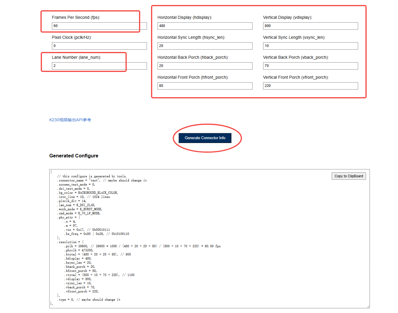
Tool Generated Code Example:
{
    // this configure is generated by tools.
    .connector_name = "test",        // Modify according to actual situation
    .screen_test_mode = 0,
    .dsi_test_mode = 0,
    .bg_color = BACKGROUND_BLACK_COLOR,
    .intr_line = 10,                 // 1024 lines
    .pixclk_div = 14,
    .lan_num = K_DSI_2LAN,
    .work_mode = K_BURST_MODE,
    .cmd_mode = K_VO_LP_MODE,
    .phy_attr = {
        .n = 4,
        .m = 97,
        .voc = 0x17,                 // 0b00010111
        .hs_freq = 0x80 | 0x26,      // 0b10100110
    },
    .resolution = {
        .pclk = 39600,               // Pixel clock: 39600 * 1000 = 39600000 Hz
        .phyclk = 475200,
        .htotal = (480 + 20 + 20 + 80),     // 600
        .hdisplay = 480,
        .hsync_len = 20,
        .hback_porch = 20,
        .hfront_porch = 80,
        .vtotal = (800 + 10 + 70 + 220),    // 1100
        .vdisplay = 800,
        .vsync_len = 10,
        .vback_porch = 70,
        .vfront_porch = 220,
    },
    .type = 0,                       // Modify according to actual situation
}
U-Boot Timing Parameter Conversion#
The correspondence between the k_connector_info structure in U-Boot and the tool generated code is as follows:
Structure Member |
Tool Field |
Description |
|---|---|---|
1st parameter |
|
Pixel clock (MHz) |
2nd parameter |
|
Physical clock (kHz) |
3rd parameter |
|
Horizontal total |
4th parameter |
|
Horizontal display |
5th parameter |
|
Horizontal sync length |
6th parameter |
|
Horizontal back porch |
7th parameter |
|
Horizontal front porch |
8th parameter |
|
Vertical total |
9th parameter |
|
Vertical display |
10th parameter |
|
Vertical sync length |
11th parameter |
|
Vertical back porch |
12th parameter |
|
Vertical front porch |
|
|
DSI PHY parameter n |
|
|
DSI PHY parameter m |
|
|
DSI PHY parameter voc |
|
|
DSI PHY parameter hs_freq |
Note: The complete form of the
k_connector_infostructure is as follows:info = (k_connector_info){ 0, // connector_name index BACKGROUND_PINK_COLOR, // bg_color 10, // intr_line 14, // pixclk_div 1, // lan_num K_DSI_2LAN, // work_mode K_VO_LP_MODE, // cmd_mode { 9, 196, 0x17, 0xa3 }, // phy_attr {n, m, voc, hs_freq} { 39600, 475200, ... }, // resolution fields };Tip: Using the tool to calculate timing parameters can avoid manual calculation errors and ensure the screen timing configuration is correct.
HDMI Support#
The K230 CANMV and K230 01 Studio platforms now support HDMI display, implemented through the LT9611 bridge chip.
Configuration file: arch/riscv/boot/dts/canaan/k230-canmv.dts
/ {
hdmi: connector {
compatible = "hdmi-connector";
label = "hdmi";
type = "a";
port {
hdmi_connector_in: endpoint {
remote-endpoint = <<9611_out>;
};
};
};
};
&i2c4 {
status = "okay";
lt9611: hdmi-bridge@3b {
compatible = "lontium,lt9611";
reg = <0x3b>;
reset-gpios = <&gpio1_ports 10 GPIO_ACTIVE_HIGH>;
interrupt-parent = <&gpio1_ports>;
interrupts = <11 IRQ_TYPE_EDGE_FALLING>;
ports {
#address-cells = <1>;
#size-cells = <0>;
port@1 {
reg = <1>;
lt9611_in: endpoint {
remote-endpoint = <&dsi_out_lt9611>;
};
};
port@2 {
reg = <2>;
lt9611_out: endpoint {
remote-endpoint = <&hdmi_connector_in>;
};
};
};
};
};
&dsi {
ports {
port@1 {
reg = <1>;
dsi_out_lt9611: endpoint {
remote-endpoint = <<9611_in>;
};
};
};
};
Key Configuration Points:
Add the LT9611 bridge chip node, configure the I2C address and GPIO reset
Establish the connection path from DSI -> LT9611 -> HDMI Connector
This configuration structure can be referenced when HDMI porting is required
Testing and Verification#
Basic Parameter Viewing#
Use the modetest tool to view all parameters of the display system:
modetest -M canaan-drm
OSD Layer Test#
# OSD layer test: overlay OSD(39) on HDMI(48), format RG16
modetest -M canaan-drm -D 0 -a -s 48@46:1920x1080 -P 39@46:640x480@RG16 -v -F tiles
LAYER Layer Test#
# LAYER layer test: overlay LAYER(43) on HDMI(48), format NV12
# Note: LAYER43 supports Rotation and Mirror functions
modetest -M canaan-drm -D 0 -a -s 48@46:1920x1080 -P 43@46:640x480@NV12 -v -F tiles
Test Parameter Description:
Parameter |
Description |
|---|---|
|
Specify DSI interface |
|
Auto-set plane |
|
Set connector mode (connector@crtc:resolution) |
|
Set plane property (plane@crtc:resolution@format) |
|
Display frame rate information |
|
Set frame buffer format |
Configuration File Reference Path#
File |
Description |
|---|---|
|
ST7701 3.5-inch screen configuration example |
|
ILI9881 8-inch screen configuration example |