
Image Flashing and Serial Port Connection#
Image Acquisition and Flashing#
Images can be generated by compiling SDK source code, or downloaded from the Kendryte SDK Image Center.
This section provides multiple flashing options. Please choose the appropriate method based on your actual needs
The image file needs to be extracted before flashing;
Flashing with a Card Reader#
After flashing is complete, insert the TF card into the development board, and connect it to the computer via USB cable (optional: press the reset button to reset);
Open the serial port software to view the output information,
For instructions on how to connect the development board and view the serial port, please refer to the following sections.
Flashing with a Card Reader under Linux#
Before inserting the TF card into the host machine (computer), check the current storage devices:
ls -l /dev/sd*
Execute the command again after inserting the TF card. The newly added device node is the TF card device.
Assuming the TF card device node is
/dev/sdc, execute the flashing command:sudo dd if=sysimage-sdcard.img of=/dev/sdc bs=1M oflag=sync
Flashing with a Card Reader under Windows#
Under Windows, it is recommended to use rufus or balenaetcher to flash the TF card,
Notes Some flashing software may have bugs. If you encounter flashing issues, it is recommended to switch flashing tools.
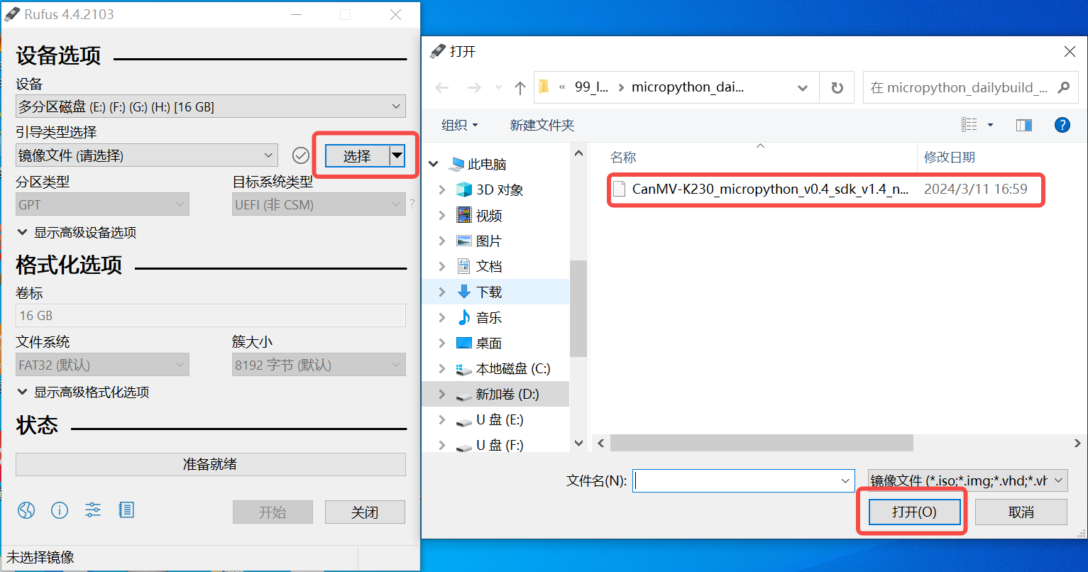
Steps for flashing with Rufus
Insert the TF card into the PC and launch the Rufus tool;
Click the “Select” button and choose the firmware image to be flashed;
After confirming that the device and image are correct, click “Start”
Computer flashing development board via USB#
For flashing via USB, please 《Refer to USB Flashing Chapter》
The above link is the supporting documentation for RTOS, only the flashing part is universal;
Development Board Connection#
Note Please use a reliable Type-C cable that supports data transfer. Cables that only support power supply are not supported. The first boot may take a few minutes for filesystem expansion. Please be patient.
JLC Lushan Pi Development Board#
Please refer to the diagram below to connect the serial port of the Lushan Pi development board:
Important Notes
The serial port only needs to connect RX (Receive), TX (Transmit), and GND (Ground) three wires;
The power wire (red wire) is strictly prohibited from being connected, as incorrect connection may cause the development board to burn out.
CanMV IDE is not supported for serial port debugging. Please use standard serial port tools (such as PuTTY, Tera Term, or minicom);
Default serial port parameters:
Baud rate: 115200
Data bits: 8
Stop bits: 1
Parity: None
Flow control: None
01studio Development Board#
Please refer to the diagram below to connect the serial port of the 01studio development board:
Serial Port Debugging Notes
CanMV IDE is not supported for serial port debugging. Please use standard serial port tools;
Default serial port parameters are the same as the table above.
CanMV-V1.0/1.1/3.0 Development Board#
Hardware Connection
Use a Type-C cable to connect the CanMV-K230 development board to the computer (as shown in the diagram below)
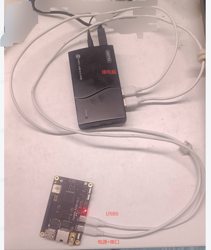
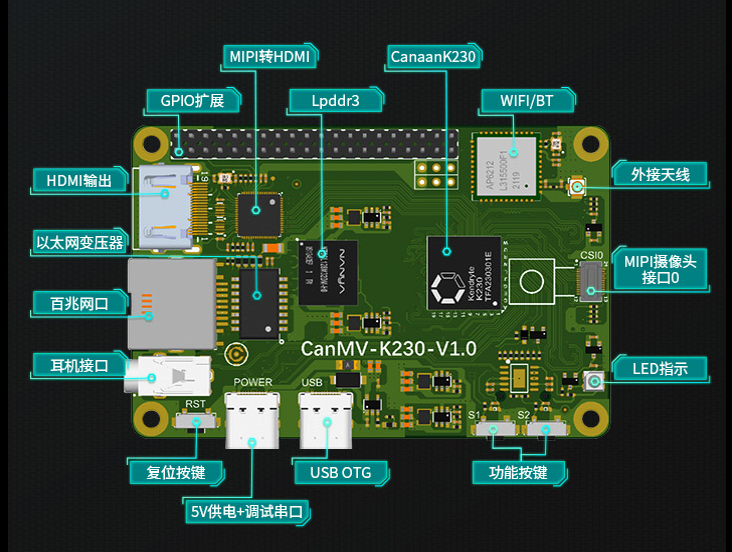
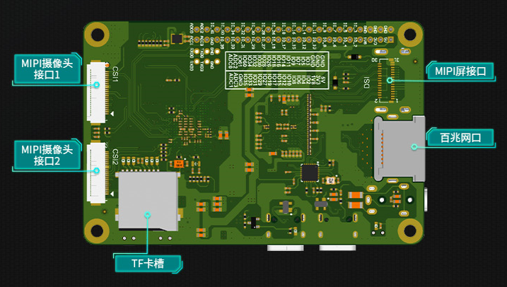
It is recommended to connect two USB cables: The first Type-C cable: used for 5V power supply and debug serial port communication; The second Type-C cable: can be used for file transfer via MTP or ADB.
Serial Port Number Confirmation
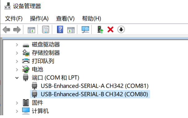
After the device is powered on, the computer will recognize two serial ports:
Windows system displays similar to the following:
Serial Port Name |
Description |
|---|---|
USB-Enhanced-SERIAL-A CH342 (COM80) |
Small core Linux debug serial port |
USB-Enhanced-SERIAL-B CH342 (COM81) |
Serial port 3 (not used yet) |
If the serial port is recognized abnormally, please reinstall the CH342/CH343 driver.
Linux system is similar to the following:
Device Node |
Description |
|---|---|
|
Small core Linux debug serial port |
|
Serial port 3 (not used yet) |
The serial port device can be recognized regardless of whether a TF card is inserted.
View Serial Port Output
Use serial port software (such as PuTTY, MobaXterm, Xshell, SecureCRT, etc.) to connect to the debug serial port to view output information.
Quick Verification When the TF card is not inserted, press the reset button, and the debug serial port will output a line of printing, indicating that the CPU is working normally. Baud rate: 115200, Data bits: 8, Stop bits: 1, Parity: None, Flow control: None
k230d-canmv Development Board#
Refer to the diagram below to connect the development board to the computer. Serial port parameters and usage methods are the same as the CanMV-V1.0/1.1/3.0 development board
Use a Type-C cable to connect the development board’s Power+UART interface to the computer:
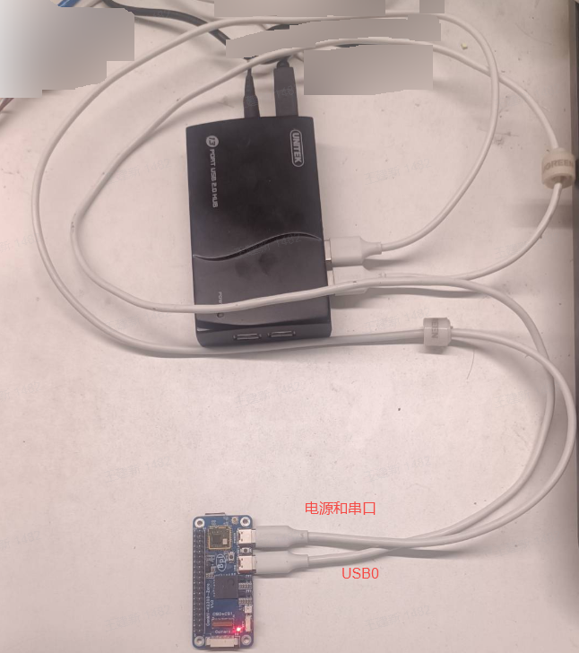
It is recommended to connect two USB cables (same as CanMV-V1.0/1.1/3.0) If the serial port is recognized abnormally, please reinstall the CH342/CH343 driver