
K230 Linux SDK New Board Adaptation Guide#
Document Purpose#
This document describes how to adapt devices that are not officially supported to the K230 Linux SDK.
Adapt Based on Existing Configuration (Recommended)#
Select a configuration whose hardware setup is close to that of the target board, and directly modify the relevant files. This chapter uses k230_canmv_01studio_defconfig as an example.
01studio Main Configuration File#
Item |
Description |
|---|---|
File Path |
|
Function |
SDK configuration file, which can enable software packages, configure rootfs size, and configure the configuration files used by U-Boot and the kernel, etc. |
Modification Method |
Modify directly, or run |
How to Take Effect |
|
Key Configuration Item Description
BR2_LINUX_KERNEL_DEFCONFIG="k230"  # Kernel default configuration file k230_defconfig
BR2_LINUX_KERNEL_CONFIG_FRAGMENT_FILES="board/canaan/k230-soc/fragment/linux.fragment"  # Kernel configuration append file
BR2_LINUX_KERNEL_INTREE_DTS_NAME="canaan/k230-canmv-01studio-lcd canaan/k230-canmv-01studio"  # Kernel device tree
BR2_PACKAGE_BUSYBOX_CONFIG_FRAGMENT_FILES="board/canaan/k230-soc/fragment/busybox.fragment"  # BusyBox configuration file
BR2_TARGET_UBOOT_BOARDNAME="k230_canmv_01studio"  # Configuration file used by U-Boot
BR2_TARGET_ROOTFS_EXT2_SIZE="400M"  # rootfs size
Key Files Under U-Boot#
U-Boot Configuration File#
Item |
Description |
|---|---|
File Path |
|
Modification Method |
Modify manually, or run |
How to Take Effect |
|
Key Configuration Item Description:
CONFIG_DEFAULT_DEVICE_TREE="k230_canmv_01studio"  # Configure the device tree file to use
CONFIG_CANMV_01STUDIO_LPDDR4_2667=y  # DDR type and frequency
CONFIG_TARGET_K230_CANMV_01STUDIO=y  # 01studio development board
U-Boot Device Tree#
Item |
Description |
|---|---|
File Path |
|
Remarks |
Determined by |
How to Take Effect |
|
Key Code Description:
// BANK voltage settings must match the board hardware, otherwise the device may be permanently damaged
#define BANK_VOLTAGE_IO0_IO1  K230_MSC_1V8  // FIXED
#define BANK_VOLTAGE_IO2_IO13  K230_MSC_3V3
#define BANK_VOLTAGE_IO14_IO25  K230_MSC_3V3
#define BANK_VOLTAGE_IO26_IO37  K230_MSC_3V3
#define BANK_VOLTAGE_IO38_IO49  K230_MSC_3V3
#define BANK_VOLTAGE_IO50_IO61  K230_MSC_3V3
#define BANK_VOLTAGE_IO62_IO63  K230_MSC_1V8

// IOMUX function configuration, adjust according to the actual board situation
// SEL field selects IOMUX function, refer to: Appendix A
(IO2) (1<<SEL | 0<<SL | BANK_VOLTAGE_IO2_IO13<<MSC | 1<<IE | 1<<OE | 0<<PU | 0<<PD | 4<<DS | 0<<ST)
(IO3) (3<<SEL | 0<<SL | BANK_VOLTAGE_IO2_IO13<<MSC | 1<<IE | 1<<OE | 0<<PU | 0<<PD | 4<<DS | 0<<ST)
(IO4) (3<<SEL | 0<<SL | BANK_VOLTAGE_IO2_IO13<<MSC | 1<<IE | 1<<OE | 0<<PU | 0<<PD | 4<<DS | 0<<ST)
(IO5) (1<<SEL | 0<<SL | BANK_VOLTAGE_IO2_IO13<<MSC | 1<<IE | 1<<OE | 0<<PU | 0<<PD | 4<<DS | 0<<ST)
(IO6) (1<<SEL | 0<<SL | BANK_VOLTAGE_IO2_IO13<<MSC | 1<<IE | 1<<OE | 0<<PU | 0<<PD | 4<<DS | 0<<ST)
Note: For IOMUX configuration, please refer to Appendix A: IOMUX Pin Configuration Description
U-Boot Board Directory#
Item |
Description |
|---|---|
Directory Path |
|
Modification Method |
Modify directly |
How to Take Effect |
|
Key File Description:
board.c: Board-level initialization filesysctl_boot_mode_e sysctl_boot_get_boot_mode(void) { return SYSCTL_BOOT_SDIO0; // Force boot from MMC0 }
lpddr4_init_32_swap_2667.c: DDR4 initialization code
Linux Key Files#
Linux Device Tree#
Item |
Description |
|---|---|
File Path |
|
Modification Method |
Direct modification |
How to Apply |
|
Other Notes |
Generated only after one compilation; filename with |
Key Configuration Snippets:
aliases {
    serial3 = &uart3;  // Define device number
    i2c0 = &i2c4;      // Define device number
    i2c1 = &i2c3;
    mmc0 = &mmc_sd0;   // Define device number
    mmc1 = &mmc_sd1;
};

&usb1 {
    dr_mode = "host";  // Force host mode
    status = "okay";   // Enable USB1
};
Kernel Configuration File Modification#
Method One: Directly add the required kernel configuration in board/canaan/k230-soc/fragment/linux.fragment.
Method Two: Execute the following commands to modify the kernel configuration:
make linux-menuconfig;
make linux-savedefconfig;
cp output/k230_test_defconfig/build/linux-*/defconfig buildroot-overlay/board/canaan/k230-soc/fragment/linux.fragment;
How to apply after modification:
make linux-reconfigure;make
Fresh Adaptation (Not Recommended)#
Note: This method is not recommended; it is preferable to directly use existing configurations and modify them.
Add Main Configuration File#
Create a configuration file in the buildroot-overlay/configs/ directory (using k230_test_defconfig as an example):
cd buildroot-overlay/configs/
cp k230_canmv_01studio_defconfig k230_test_defconfig
cd ../../
make CONF=k230_test_defconfig
U-Boot Adaptation#
Step 1: Add Board-Level Directory#
cd buildroot-overlay/boot/uboot/u-boot-2022.10-overlay/board/canaan/
cp k230_canmv_01studio k230_test -r
cd -
Step 2: Modify Kconfig#
Add the following to
buildroot-overlay/boot/uboot/u-boot-2022.10-overlay/arch/riscv/Kconfig:
#buildroot-overlay/boot/uboot/u-boot-2022.10-overlay/arch/riscv/Kconfig file
#around line 50
config TARGET_K230_TEST
    bool "Support TEST BOARD"
    select SYS_CACHE_SHIFT_6

#around line 112
source "board/canaan/k230_test/Kconfig"
Modify the
board/canaan/k230_test/Kconfigfile, ReplaceTARGET_K230_CANMV_01STUDIOwithTARGET_K230_TEST, similar to the following:
if TARGET_K230_TEST
#......
config SYS_BOARD
    default "k230_test"
#......
endif
Step 3: Add and Modify U-Boot Device Tree#
Add a new device tree:
cd buildroot-overlay/boot/uboot/u-boot-2022.10-overlay/arch/riscv/dts/
cp k230_canmv_01studio.dts k230_test.dts
cd -
Modify the device tree. Key modification points are as follows:
// BANK voltage settings must match the board design; incorrect configuration may damage the chip
#define BANK_VOLTAGE_IO0_IO1           K230_MSC_1V8  // FIXED
#define BANK_VOLTAGE_IO2_IO13          K230_MSC_3V3
#define BANK_VOLTAGE_IO14_IO25         K230_MSC_3V3
#define BANK_VOLTAGE_IO26_IO37         K230_MSC_3V3
#define BANK_VOLTAGE_IO38_IO49         K230_MSC_3V3
#define BANK_VOLTAGE_IO50_IO61         K230_MSC_3V3
#define BANK_VOLTAGE_IO62_IO63         K230_MSC_3V3
#include "k230.dtsi"

&mmc0 {
    1-8-v;          // Configure MMC0 as 1.8V IO
    status = "okay";
};

&mmc1 {
    status = "okay";
};

&iomux {
    pinctrl-names = "default";
    pinctrl-0 = <&pins>;

    pins: iomux_pins {
        u-boot,dm-pre-reloc;
        pinctrl-single,pins = <
            (IO2)  (1<<SEL | 0<<SL | BANK_VOLTAGE_IO2_IO13<<MSC | 1<<IE | 0<<OE | 0<<PU | 1<<PD | 4<<DS | 1<<ST)
            (IO63) (0<<SEL | 0<<SL | BANK_VOLTAGE_IO62_IO63<<MSC | 1<<IE | 1<<OE | 0<<PU | 0<<PD | 7<<DS | 1<<ST)
        >;
    };
};
Note: For IOMUX configuration, please refer to Appendix A: IOMUX Pin Configuration Description
Step 4: Add and Modify U-Boot Configuration File#
Add configuration file
cd buildroot-overlay/boot/uboot/u-boot-2022.10-overlay/configs/
cp k230_canmv_01studio_defconfig k230_test_defconfig
cd -
Modify configuration items, key modification points:
CONFIG_DEFAULT_DEVICE_TREE="k230_test"
CONFIG_TARGET_K230_TEST=y
CONFIG_CANMV_01STUDIO_LPDDR4_2667=y
Step 5: Modify SDK Configuration#
Modify the buildroot-overlay/configs/k230_test_defconfig file:
Change BR2_TARGET_UBOOT_BOARDNAME to “k230_test”
BR2_TARGET_UBOOT_BOARDNAME="k230_test"
Step 6: Build and Verify#
# Enter the SDK main directory and execute the following commands
make k230_test_defconfig
make uboot-dirclean
make uboot
Linux Adaptation#
Step 1: Add Device Tree#
cd output/k230_test_defconfig/build/linux-*/arch/riscv/boot/dts/canaan/
cp k230-canmv-01studio.dts k230-test.dts
cd -
Key Configuration Examples:
aliases {
    serial3 = &uart3;
    i2c0 = &i2c4;
    i2c1 = &i2c3;
    mmc0 = &mmc_sd0;
    mmc1 = &mmc_sd1;
};

&usb1 {
    dr_mode = "host";
    status = "okay";
};

&mmc_sd0 {
    status = "okay";
    io_fixed_1v8;           // Configure MMC0 as 1.8V IO
    rx_delay_line = <0x0d>;
    tx_delay_line = <0x40>;
};
Step 2: Switch Device Tree#
Modify buildroot-overlay/configs/k230_test_defconfig:
Change BR2_LINUX_KERNEL_INTREE_DTS_NAME to “canaan/k230-test”
BR2_LINUX_KERNEL_INTREE_DTS_NAME="canaan/k230-test"
Step 3: Modify Kernel Configuration File#
Refer to the Kernel Configuration File Modification section above.
Development Board OTP Burning#
OTP Description#
K230/K230D integrates a One Time Programmable (OTP) device internally. This device can store permanent binding information such as MAC, boot parameters, etc. Usually, we store the boot configuration in it.
!!! Burning incorrect OTP or firmware voltage configuration that does not match the hardware configuration may cause the chip to be burned out!!!
Automatically Generate OTP Configuration bin File Based on Hardware Settings#
Canaan provides a convenient graphical WEB interface to automatically generate the OTP configuration bin file. During this process, it is essential to fully communicate with the hardware engineer to clarify hardware settings and voltage settings and other key information.
Configuration tool link: OTP Configuration Tool
When generating the bin file, you need to carefully select the corresponding configuration based on the hardware schematic:
UART IOMUX used by BOOT ROM printing: This option is used to select the serial port for BOOT log output (it is recommended to prioritize UART0)
UART voltage used by BOOT ROM printing: The voltage used by the BOOT output serial port
OSPI IO voltage: Voltage of the OSPI domain
SDIO0 IO voltage: Voltage of the MMC0 domain
SDIO1 IOMUX: Pins selected by MMC1
SDIO1 IO voltage: Voltage of the MMC1 domain
Taking the 01Studio development board schematic as an example, the options can be determined based on these parts:
Based on the above information, the OTP configuration for 01Studio should be as follows
Special reminder: Be sure to repeatedly verify the accuracy of the configuration with the hardware engineer. Once the configuration is incorrect and the burning operation is performed, it is very likely to cause permanent damage to the chip, which cannot be repaired!
After completing the above configuration, click the “Generate Configuration File” button to generate a bin file, as shown in the example below:
If the interface prompts “The settings are consistent with the default configuration, no need to generate a configuration file”, it means that the default OTP can work and there is no need to re-burn the OTP. Please skip the OTP burning chapter.
Burn OTP bin File#
Burning tool download link: Kendryte Developer Community - Resource Download
Please select the corresponding version for download according to the operating system you are using. At the same time, please be sure to note: Do not power the development board for a long time before the OTP burning is completed, to avoid chip burning.
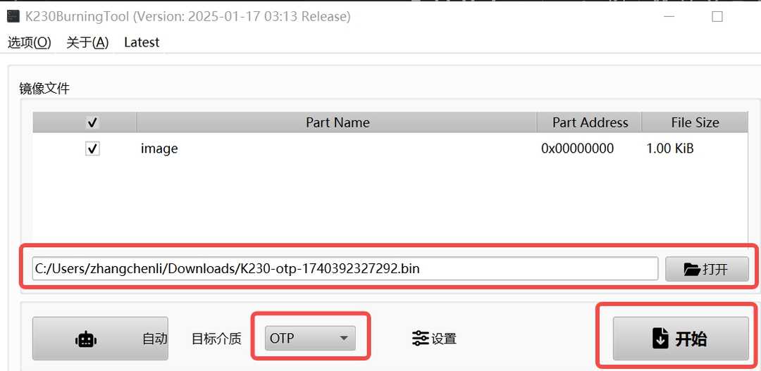
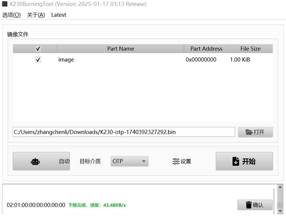
Power on the chip, connect the UART0 interface, open the BurningTool software, and select the previously generated bin file:
Click the “Start” button and patiently wait for the burning process to finish:
After burning is complete, click “Confirm”.
Appendix A: IOMUX Pin Configuration Description#
This chapter describes the iomux configuration under uboot For iomux under linux, please refer to K230 linux IOMUX Guide
Configuration Principles#
IOMUX configuration needs to refer to the board schematic and iomux table
Unused pins are recommended to be configured as GPIO to avoid function conflicts
Configuration Parameter Description#
The following uses IO7 configured as I2C4_SCL as an example:
(IO7) (2<<SEL | 0<<SL | BANK_VOLTAGE_IO2_IO13<<MSC | 1<<IE | 1<<OE | 1<<PU | 0<<PD | 7<<DS | 1<<ST)
Parameter |
Description |
Example |
|---|---|---|
SEL |
Function number selection, starting from 0 (Function Number - 1 in the iomux table) |
I2C4_SCL corresponds to |
SL |
Output slew rate control, configurable only for IO0/IO1 single voltage PAD |
|
MSC |
Operating voltage configuration, must be consistent with the board BANK power supply |
|
IE |
Input enable, 0 means input direction is invalid |
|
OE |
Output enable, 0 means output direction is invalid |
|
PU |
Pull-up configuration, recommended to enable for I2C and other buses |
|
PD |
Pull-down configuration, related to functional requirements |
|
DS |
Drive strength configuration, IO2~IO63 are all dual voltage PADs (16 drive) |
|
ST |
Schmitt trigger configuration, generally configured as 1 |
|
Drive Strength Description#
Single voltage PAD: 8 drive, 3bit effective, value range
0x0~0x7Dual voltage PAD (IO2~IO63): 16 drive, 4bit effective, value range
0x0~0xF