
UART Example#
Introduction#
This example is a cross-loopback test program for UART2 and UART3, covering multiple baud rates, parity, stop bits, polling, buffers, and stress tests.
Source location: src/rtsmart/examples/peripheral/uart/test_uart.c
Serial Port Levels and Adapter Module Safety#
Warning
Before connecting any USB-to-UART module or serial peripheral, you must first consult the development board schematic to confirm the I/O domain voltage corresponding to the UART pins used. The K230’s I/O domain may be configured for 1.8 V or 3.3 V, and different development boards and pins may differ. The external device’s TX/RX logic levels must match those of the development board; a level-shifting circuit must be added when they do not match. Connecting 5 V UART signals directly to the K230 is prohibited.
Please make connections while the power is off, and ensure that TX is connected to RX, RX is connected to TX, and GND is shared. Unless explicitly required by the development board documentation, do not connect the VCC/5V pin of the USB-to-serial module. For specific electrical restrictions, please refer to the K230 Hardware Design Guide.
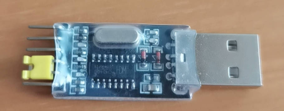
Do not use the CH340G USB-to-serial module with the yellow jumper cap shown in the figure below. Even when the 3.3 V setting is selected, the TX high level of some samples of this low-quality module may still reach approximately 3.8 V, posing a risk of permanently damaging the K230, especially in the 1.8 V I/O domain. This warning applies specifically to the module shown below and does not disparage all products using the CH340G chip. Use a genuine module whose levels have been verified; it is recommended to measure the module’s TX idle high level before the first connection.
Example Behavior#
Fixed pin mapping:
UART2: TX=11, RX=12
UART3: TX=50, RX=51
Automatically configures multiple groups of parameters for batch testing (baud rate/parity/stop bits)
Performs basic send/receive, poll, recv_available, configuration read/write, and random stress tests
Summarizes pass/fail results for each configuration group
Key Interfaces#
drv_uart_inst_create()/drv_uart_inst_destroy()drv_uart_set_config()/drv_uart_get_config()drv_uart_write()/drv_uart_read()drv_uart_poll()/drv_uart_recv_available()drv_uart_configure_buffer_size()drv_fpioa_set_pin_func()
Build and Run#
cd src/rtsmart/examples/peripheral/uart
make
./test_uart
This example has no command-line arguments.
Tip
For UART interface details, please refer to UART API Documentation.