
FPIOA Usage Tutorial#
Overview#
In embedded systems, SoC (System on Chip) typically integrates multiple peripheral modules, such as UART, SPI, I2C, PWM, and GPIO, etc. However, due to the limited number of physical pins, these modules often need to share pins. To resolve this conflict, the IOMUX (pin multiplexing) mechanism is required. In the K230 chip, this mechanism is called FPIOA (Field Programmable IO Array).
FPIOA allows us to assign the required function to any pin. For example, you can set pin 10 as the transmit pin of UART0, or configure it as GPIO for general-purpose input/output.
What is the purpose of FPIOA?
Enhance flexibility: Developers can freely assign pin functions according to actual application requirements.
Reduce restrictions: A single hardware set can adapt to multiple pin configurations, facilitating modular design.
FPIOA Usage Example#
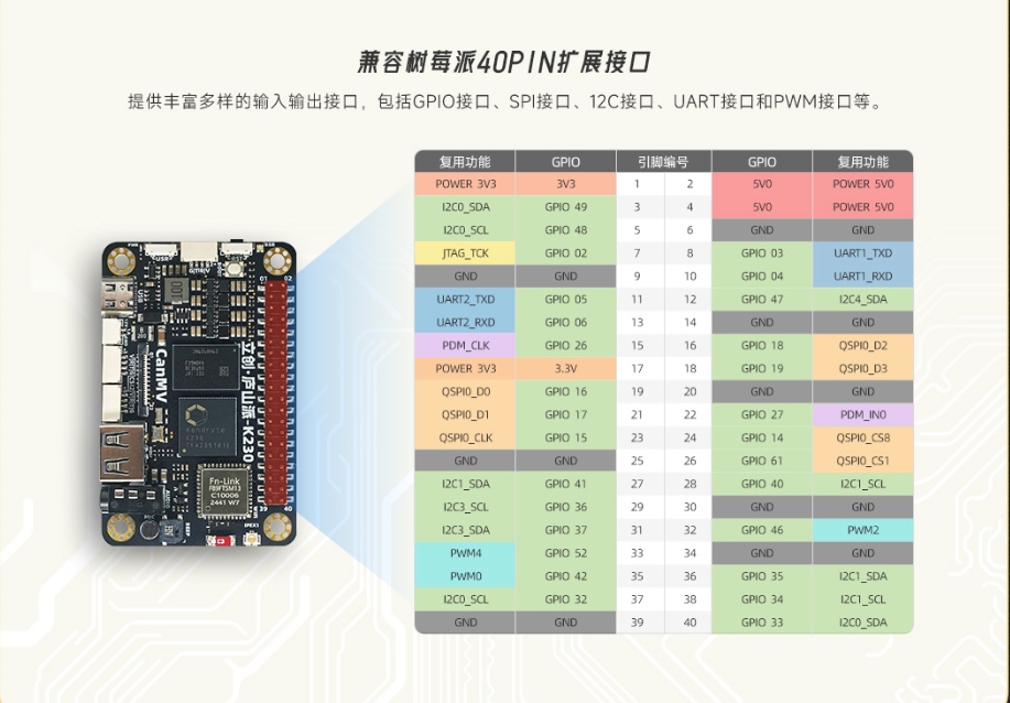
The K230 chip has multiple built-in peripheral resources, including 5 UARTs, 5 I2Cs, 6 PWMs, and up to 64 GPIO outputs, etc. These peripherals achieve pin multiplexing through FPIOA, so different manufacturers’ K230 development boards may have different pin assignment schemes. These manufacturers generally provide corresponding development board interface documentation for reference during software development.
We use the LC·庐山派K230CanMV Development Board as an example for illustration. This development board provides an interface definition diagram, as shown below:
View the Current Function Status of All Pins#
Use fpioa.help() to view the current configuration of all pins:
from machine import FPIOA

fpioa = FPIOA()
fpioa.help()
The output is as follows:
| pin  | cur func   |                can be func                              |
| ---- |------------|---------------------------------------------------------|
| 0    | GPIO0      | GPIO0/BOOT0/RESV/RESV/RESV                              |
| 1    | BOOT1      | GPIO1/BOOT1/RESV/RESV/RESV                              |
| 2    | JTAG_TCK   | GPIO2/JTAG_TCK/PULSE_CNTR0/RESV/RESV                    |
| 3    | JTAG_TDI   | GPIO3/JTAG_TDI/PULSE_CNTR1/UART1_TXD/RESV               |
| 4    | JTAG_TDO   | GPIO4/JTAG_TDO/PULSE_CNTR2/UART1_RXD/RESV               |
| 5    | JTAG_TMS   | GPIO5/JTAG_TMS/PULSE_CNTR3/UART2_TXD/RESV               |
| 6    | JTAG_RST   | GPIO6/JTAG_RST/PULSE_CNTR4/UART2_RXD/RESV               |
| 7    | IIC4_SCL   | GPIO7/PWM2/IIC4_SCL/RESV/RESV                           |
| 8    | IIC4_SDA   | GPIO8/PWM3/IIC4_SDA/RESV/RESV                           |
| 9    | GPIO9      | GPIO9/PWM4/UART1_TXD/IIC1_SCL/RESV                      |
| 10   | GPIO10     | GPIO10/CTRL_IN_3D/UART1_RXD/IIC1_SDA/RESV               |
| 11   | GPIO11     | GPIO11/CTRL_O1_3D/UART2_TXD/IIC2_SCL/RESV               |
| 12   | GPIO12     | GPIO12/CTRL_O2_3D/UART2_RXD/IIC2_SDA/RESV               |
| ...  | ...        | ...                                                     |
Set the Target Function of a Pin#
Suppose we want to set IO11 and IO12 as I2C interfaces (I2C2) for connecting external I2C devices. According to the pin function table, they are GPIO by default and need to be reconfigured.
fpioa.set_function(11, FPIOA.IIC2_SCL, pu=1)  # Enable pull-up
fpioa.set_function(12, FPIOA.IIC2_SDA, pu=1)
After setting, we can check whether the status takes effect through help():
fpioa.help(11)
fpioa.help(12)
The output is as follows:
|pin num         |11                                                           |
|current config  |IIC2_SCL,ie:1,oe:1,pd:0,pu:0,msc:0-3.3,ds:7,st:1,sl:0,di:1   |
|can be function |GPIO11/CTRL_O1_3D/UART2_TXD/IIC2_SCL/RESV                    |
At this point, the interface can be used through machine.I2C(2).
Set the Electrical Properties of a Pin#
In addition to function settings, FPIOA also supports setting electrical parameters:
fpioa.set_function(2, FPIOA.GPIO2, ie=1, oe=1, pu=0, pd=0, st=1, ds=7)
fpioa.help(2)
For more detailed configuration of electrical parameters, please refer to K230 IOMUX Configuration Tool
Get the Correspondence Between Functions and Pins#
Query the pin number corresponding to a function:
fpioa.get_pin_num(FPIOA.UART0_TXD) # → 38
Query the function number of the current pin configuration:
fpioa.get_pin_func(0) # → 0
Frequently Asked Questions FAQ#
Q1: I don’t know which pins a certain function can be mapped to. What should I do?#
You can use help() to query all pins supported by that function:
fpioa.help(FPIOA.IIC0_SDA, func=True)
Output:
function IIC0_SDA can be set to PIN33, PIN49, PIN61
current set PIN49 as IIC0_SDA
For more pin function correspondence tables, please refer to the official documentation: K230 Chip Pin Definition List
Q2: I have set the pin function, but communication is still not working normally. What could be the reason?#
Please confirm the following:
Whether the selected pin supports that function
Whether the pin is already occupied by another module
Whether input/output enable (
ie/oe) is correctly setWhether pull-up/pull-down resistors need to be enabled (especially for I2C)