
UART Usage Tutorial#
What is UART?#
UART (Universal Asynchronous Receiver/Transmitter) is a common serial communication protocol used to send and receive data between devices in a serial manner. It is widely used for:
Serial terminal debugging
Communication with sensors or external modules (such as GPS, GSM modules)
Data exchange between master and slave devices
Serial Port Level and Adapter Module Safety#
Warning
Before connecting any USB-to-UART module or serial peripheral, you must first consult the development board schematic to confirm the I/O domain voltage corresponding to the UART pins used. The I/O domain of the K230 may be configured as 1.8 V or 3.3 V, which may vary across different development boards and different pins. The TX/RX logic levels of the external device must match the development board; if they do not match, a level-shifting circuit must be added. Do NOT connect 5 V UART signals directly to the K230.
Please power off before wiring, and ensure that TX connects to RX, RX connects to TX, and GND is shared. Unless explicitly required by the development board documentation, do not connect the VCC/5V pin of the USB-to-serial module. Please refer to the K230 Hardware Design Guide for specific electrical limits.
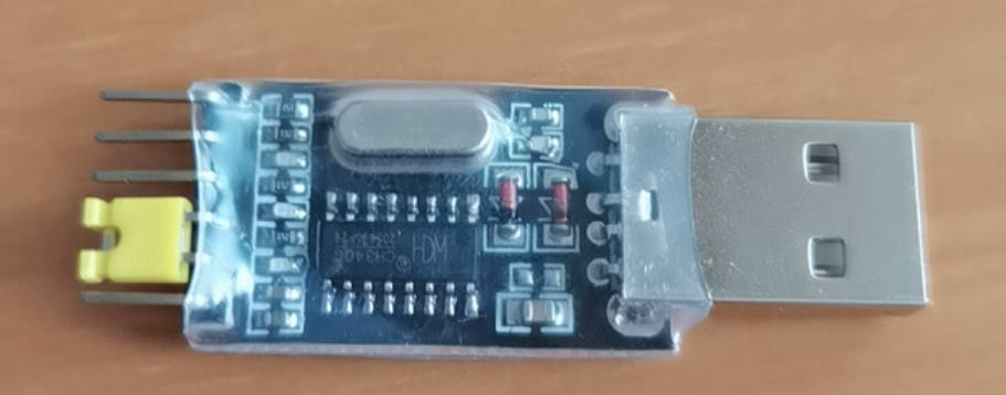
Do NOT use the CH340G USB-to-serial module with a yellow jumper cap as shown in the figure below. With such low-quality modules, even if the 3.3 V setting is selected, the TX high level of some samples may still reach approximately 3.8 V, which poses a risk of permanently damaging the K230, especially dangerous on the 1.8 V I/O domain. This warning is directed at the module shown in the figure below, not at all products using the CH340G chip. You should use a regular module with verified levels; before the first connection, it is recommended to measure the module’s TX idle high level.
K230 UART Features#
Feature |
Description |
|---|---|
Number of supported channels |
5 UARTs: UART0 ~ UART4 |
Available channels description |
UART0 is occupied by system debugging, UART1, 2, 3, 4 are available |
Configurable parameters |
Baud rate, data bits, stop bits, parity bit, etc. |
Pin multiplexing |
Supports setting any IO as UART function via IOMUX |
Data operation methods |
Supports methods such as |
Application Example: Serial Send/Receive Test#
The following example demonstrates how to initialize the UART1 interface and perform data sending and receiving operations.
Example Code#
from machine import UART

# ========== Initialize UART1 ==========
u1 = UART(
    UART.UART1,           # UART1 channel
    baudrate=115200,      # Baud rate 115200
    bits=UART.EIGHTBITS,  # 8 data bits
    parity=UART.PARITY_NONE,  # No parity
    stop=UART.STOPBITS_ONE    # 1 stop bit
)

# ========== Send data ==========
u1.write("UART1 test")  # Send string

# ========== Read data ==========
r = u1.read()            # Read received byte data (may be None)
r = u1.readline()        # Read a whole line (terminated by newline)
b = bytearray(8)
u1.readinto(b)           # Fill received data into the bytearray

# ========== Release resources ==========
u1.deinit()
Interface Description#
Method Name |
Description |
|---|---|
|
Create a UART object, specifying the channel number and communication parameters |
|
Write a string or byte data to the serial port |
|
Read all available data, return a bytes object or None |
|
Read one line of data, terminated by a newline character |
|
Read data into the specified buffer (such as |
|
Stop the serial port and release resources |
Application Scenario Examples#
Serial debug output: replace
print(), making it easier for external devices to monitor logsCommunicate with serial modules: such as Bluetooth, LoRa, 4G modules
Multi-serial concurrent task processing: connect multiple peripherals through UART1/2/4
Troubleshooting#
Issue |
Troubleshooting Suggestions |
|---|---|
Unable to receive data |
Check the baud rate settings and whether the IO mapping is correct |
Received data is garbled |
Confirm that the communication parameters on both ends are consistent (baud rate, data bits, etc.) |
Read result is None |
There is no readable data in the serial port buffer |
UART0/UART3 cannot be used |
These two channels are occupied by the system; it is recommended to use UART1/2/4 |